
FDO Reader Documentation
Good to know
The v8i version is maintained but little or no functionality will be added.
- Only the CONNECT version supports writing (beta).
- The CONNECT version uses Item Types, the v8i version uses EC-Attributes.
- The CONNECT version support PickLists for attributes.
- The 64-bit version for CONNECT is slightly faster than the 32-bit version for v8i.
This is due to the fact that the C# api is more efficient in MicroStation CONNECT.
Installation
MicroStation v8i
Download the complete project and run the file setup_fd032_v1.0.exe.
The file need to be run as Administrator since the program is installed for the local machine, not the current user. The setup will ask for raised privileges.
If you have a serial number this should be provided during installation. If a valid serial number is not entered the program be converted to demo mode after 30 days.
Accept the default installation folder or select another location. The files may be moved after installation.
If this is the first time the program is installed both the FDO Reader and the Providers should be selected during install. The Example data is optional.
After a succesfull install the FDO Reader should be updated. Download the latest version by selecting FDO Reader only from the Download page. Replace the files FDO32.dll.
MicroStation CONNECT beta
Download the complete CONNECT setup and run the installer.
Update the installation by downloading FDO CONNECT Only. This archive contains the latest version and can be used to update the FDO files after installing the project. Replace the corresponding files in the mdlapps directory.
Additional Providers
Additional Data Providers are provided through OSGeo.org , ie as open source. These are available in 32-bit and 64- bit versions and can be downloaded at http://fdo.osgeo.org/content/downloads. The v8i version uses FDO version 3.6.0 and the CONNECT version uses FDO version 4.0.0.
Download and unpack the files and put them in the directory specified by MS_ADDINPATH.
Network install
MicroStation FDO Reader is a C# program and there might be problem running the software from a network drive due to .NET security issues. Please read https://support.microsoft.com/en-us/kb/832742 for more information.
Start the program
If MS_DGNAPPS is not defined the program is loaded by the following keyin:
mdl load fdo32
To open the dialog the following command is used:
fdo dialog
![]()
If no default map is specified (see Configuration variables), the dialog will be empty.
Open a datasource
To open a data store click the icon ”Open Datasource”. When a data source is loaded a map layer will be created for each table, view or feature in the data source.
Select the desired provider from the dropdown list. Remember that only Oracle, Shape, WFS, ODBC and PostGres is delivered with the demo.
Enter connect parameters for the datasource. Each datasource has a different set of parameters. Some examples is listed below.
Oracle
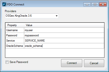
If OracleSchema is defined only the tables belonging to that schema is listed. If empty all tables visible to the user is listed.
Read more about this provider at http://www.sl-king.com/fdooracle/
SQL Server
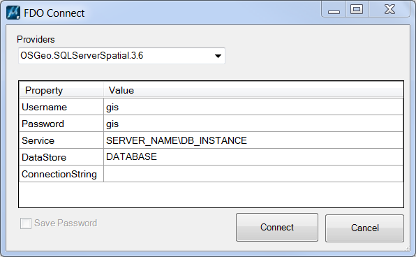
Read more about the provider at https://trac.osgeo.org/fdo/wiki/FdoSQLServerSpatialNotes and http://fdo.osgeo.org/sites/fdo.osgeo.org/files/docs/Providers/SQLServerSpatial/index.htm.
Shape
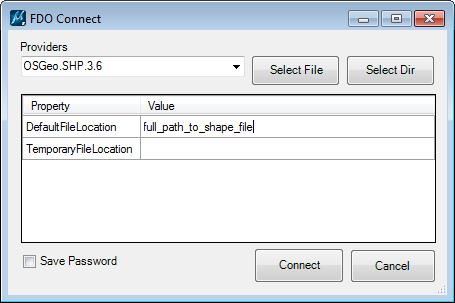
DefaultFileLocation specifies either a single shape file or an entire directory. Use the buttons or enter the filepath directly.
TemporaryFileLocation is optional an specifies a directory where FDO stores temporary files.
Read more about this provider at https://fdo.osgeo.org/fdoshp/index.html.
PostGres
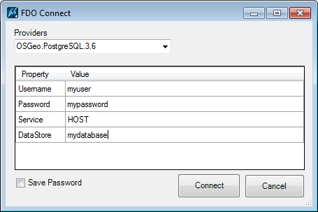
Service could be ”localhost” or a hostname folloed by a port number, e.q: myhost:4096.
Read more about this provider at https://trac.osgeo.org/fdo/wiki/FdoPostgreSQLNotes.
WFS
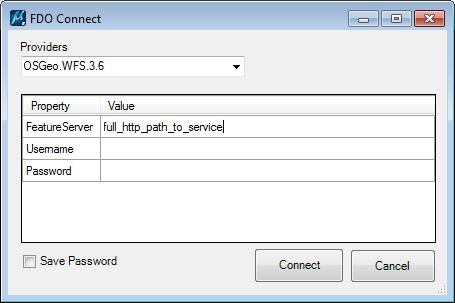
FeatureServer is the full url to the service. E.g:
http://mrdata.usgs.gov/services/mt?request=getcapabilities&service=WFS&version=1.0.0&
Read more about this provider at https://fdo.osgeo.org/fdowfs/index.html
OGR
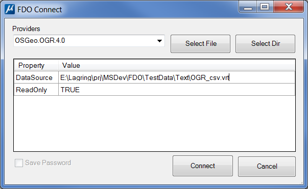
DataSource is the path to the vrt-file (Virtual Vector Format) that specifies the OGR connection.
The vrt file can define all the formats supported by OGR. Following is an example of a CSV-connection:
<?xml version="1.0"?>
<OGRVRTDataSource>
<OGRVRTLayer name="Parking_meters">
<SrcDataSource relativeToVRT="1">Parking_meters.csv</SrcDataSource>
<SrcLayer>Parking_meters</SrcLayer>
<GeometryType>wkbPoint</GeometryType>
<GeometryField encoding="PointFromColumns" x="X" y="Y"/>
</OGRVRTLayer>
</OGRVRTDataSource>
Not all OGR supported formats will work with the FDO Provider.
Read more about OGR and VRT-files at http://www.gdal.org/drv_vrt.html.
ODBC
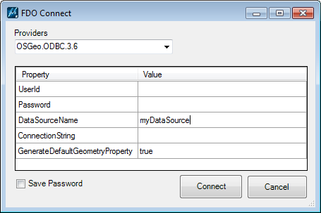
DataSourceName is the only required parameter. Enter the name of the ODBC data source.
If you use the 64-bit version the 64-bit ODBC is required.
Read more about this provider at https://fdo.osgeo.org/fdordbms/index.html.
Open a Map definition
To open an existing map click ”Open Map Definion” and select a file.
The maps can be either MicroStation FDO maps or Topocad maps. A couple of examples are included in the demo. All existing maps will be listed in the drop down menu for easy access.
A default map ca be specied using the configuration variable FDO_DEFAULT_MAP (see Configuration variables). The default map will always be loaded when the dialog is opened.
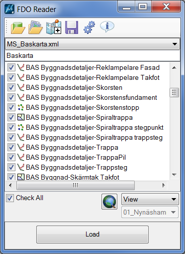
Load data
Clicking the button [Load] will load the active map or data source for the selected area. Make sure a suitable area is selected to avoid reading to much data.
The geographic area is specified from the list under the map layers.
Select View, Fence, Map View or All from the list.
The icon left of the list makes it possible to specify the area and the function depends on the selected area type. Clicking the button [Define Area] has the following functions:
View: Opens Saved View dialog
Fence: Starts the command Create Fence
Map View: Opens the Define Map View dialog
All: No command defined
Map Views are named areas that are saved in a file called FdoMapViews.xml. Map Views can be created, deleted and modified using the dialog Define Map View which is opened by clicking Define Area when active area is Map View.
Levels
A dgn level is created for each map layer. The symbology of the map layer is used to define the level. All elements will have the symbology set to ByLevel. The level description is set to layer type (Point, Line Polygon etc).
Edit a map layer
Map layers can be copied, deleted and edited. Right click on a map layer in the list to select operation.
When Edit is selected a new dialog is displayed.
Use this dialog to change the name or any other parameter for the layer.
Common parameters
Connection, Feature Class and Layer Type cannot be changed.
Prefered Type
If the layer contains several geometry types this setting can be used to limit the display to the selected type only. If set to Mixed, all geometry types will be read.
Layer Name
Set to the file or table name by default. Can be changed to any valid MicroStation level name.
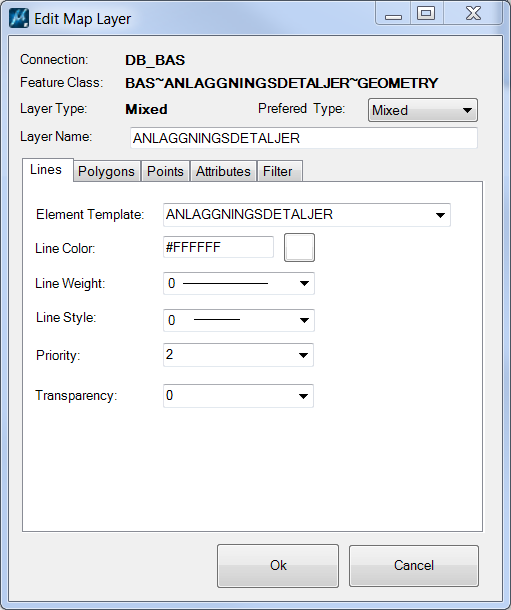
Lines
These are parameters common to all geometries.
Element Template
If an Element Template with this name exists it will be used for all element settings. By default set to the same name as the layer.
Line Color, Line Weight, Line Style, Priority, Transparency
Standard MicroStation attributes for the created element.
Polygons
For polygons fill color can be definied.
Define Fill Type and Fill Color.
Points
Point geometries can be displayed as point elements, cells or text.
Point
No additional parameters.
Text
Rotation Column
Select the column used for specifying rotation.
Optional.
Text Column
The column containing the text to be displayed.
Text Style
Text Style used to display the element.
Optional.
Font
Optional. Not used if a Text Style is specified.
Text Size
Text size is given in Master Units.
Optional. Not used if a Text Style is used.
Justification
Optional. Not used if a Text Style is used.
Symbol
Symbol
Cellname. Select from list.
Scale
Cell scale.
Optional.
Rotation Column
Select the column used for specifying rotation.
If Text is selected for a non point geometry layer the selected text will be displayed at the center of the geometry.
Attributes
Currently only used to turn attributes on and off.
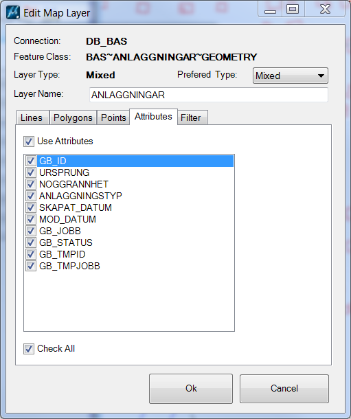
If ”Use attributes” is checked each geometry will have all attributes attached. If unchecked no attributes will be created for geometries on this map layer.
This can be overriden by the global setting ”Use Attributes” in the settings dialog.
Filter
To select a subset of a table a SQL-filter can be defined.
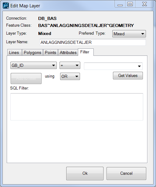
Select column and criteria by using the lists.
The button [Get Values] can be used to obtain a list of unique values from the selected column.
[Add to Filter] will add the current critera to the filter.
The SQL-filter can also be specified by typing directly into the textbox.
Note: Not all SQL-statements can be used in the filter due to limitations in the FDO-Api.
Global filters
If the same critera should be included in every filter (e.q. STATUS=0) this can be set in a global SQL. This is done under Settings (se below).
Add a map
You can add new maps to the current map. These maps can be either pre-configured maps or new data sources.
Click the icon Add New Map.
This will open a new dialog where data sources and maps can be opened.
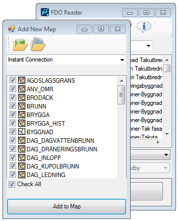
Open a new data source or an existing map.
Check all layers or only the layers you wants to add to the current map.
Click [Add to Map] to add the checked layers to the current map. The layers will be appended to the end of the map.
Save a map
To save any changes to the map layers click on the icon [Save Map Definition]. The name of the map can be set by editing the textfield before clicking on the Save icon.

Enter a filename for the new map and select Save.
Only the checked layers will be saved!
Settings
Click [Settings] to open the Settings dialog.

Active Map
Output model
It is possible to specify an other output model for the reader than the active model. If and output model is specified all reads will go to the specified model and that model will also be attached as a reference to the active model.
Clear model
If checked and an output model is specified this will clear the output model before each new read.
Use Attributes
Attributes can be read and attached to the geometries. If no attributes are needed unchecking this option will speed up reading significantly.
- Always – always attach attributes (default)
- Never – never attach attributes
- Use MapLayer – map layer settings decides
The configuration variable FDO_USE_ATTRIBUTES can be used to set a default values. See Configuration variables.
Global SQL
A part from specifying SQL-filters for individual layers a global SQL-filter can be definied. This could be used if all layers have should be filtered using the same criteria, e.q. to select only layers with a specific date or status.
Reader
Use index colors
Since all colors in the map definitions are RGB-colors this could cause problems when changing background color or exporting to dwg. This option makes it possible to select index colors for white, black or both. Settings this to index color will set the color value (blac, white, both) to index 0.
Auto increment color
When reading a data source all layers are black by default. To make it easier to differentiate layers from start each layer gets a unique color and fill color if this option is checked. Points are also set to weight 5 for visibility.
This settings is only applied when a layer is created, ie. when the data source is read. Changing this settings after the data source has been read will have no affect the layers.
Create Layers Only
This could be used to create level standards. All levels will be created using the settings for the map layer but no geometries will be read.
Speed Reader
This is the fastest way to read geometries. No attributes, levels or formatting is done.
This will override the setting ”Use Attributes”.
View Update Interval
This will set the number of elements that should be created before updating the view. This is useful for showing progress when reading large data sets. Using a low value will increase updates and slow down reading. A value between 1000 and 5000 could be a good start. Default is 0, i.e. no view updates during read.
Configuration variables
You can define configuration variables to configure the behaviour of the MicroStation FDO Reader.
# Default directory for saving and opening map definitions
FDO_MAP_DIR = $(PROJDIR)/data/
# (Optional) Directory for map definitions in the FDO dialog menu.
# Default will be the same as the FDO_MAP_DIR
FDO_MAP_LIST_DIR = $(PROJDIR)/data/
# Default map definition file
# (Optional) If defined, this map will be loaded automatically
# If no file path is definied it will default to FDO_MAP_LIST_DIR
FDO_DEFAULT_MAP = StandardMap.xml
# (Optional) Map view file. Default is $(FDO_MAP_LIST_DIR)FdoMapViews.xml
FDO_DEFAULT_MAPVIEW = C:/FDO/MyViews.xml
# (Optional) Default text size
# Text size when nothing else is specified. Default is 1.0.
FDO_MAP_DEFAULT_TEXT_SIZE = 2.5
# (Optional) Color settings for black and white colors
# 0 = use RGB (default), 1 = use index for white, 2 = use index for black, 3 use index for both
FDO_USE_INDEX_COLOR = 3
# (Optional) Default connection
# The actual parameters depends on the provider specified in the first parameter
# Provider;user;password;service;schema;
FDO_DEFAULT_CONNECT = OSGeo.KingOracle.3.8:username=myuser;password=mypassword;service=mydatabase;oracleschema=myschema;
# (Optional) Create attributes or not. 0 = Always create attributes (default), 1 = Never create attributes, 2 = MapLayer decides
FDO_USE_ATTRIBUTES = 1
# (Optional) View update interval specified by number of elements
# Default is 0 which means that the view is updated after the layer has been read
FDO_VIEW_UPDATE_INTERVAL = 3000
# (Optional) If set (any value will do) , this will rotate all texts to a readable angle from left to right
FDO_ROTATE_TEXT = 1
# (Optional) Output model for created elements.
# Default will be active model
FDO_OUTPUT_MODEL = FDO
# (Optional) Should output model be cleared before new read (0 = no, 1 0 = yes).
# Only used if FDO_OUTPUT_MODEL is specified. Default is True
FDO_CLEAR_OUTPUT_MODEL = 1
If output is written to a references model (see Settings) it is a recommended to set the following MicroStation variable:
MS_LEVEL_AUTO_SYNC_ATTRIBUTE_LIST > ByLevelSymbology, ByLevelColor, ByLevelStyle, ByLevelWeight
This make sure that any changes to symbology in reference files is displayed.